Designing an 8-bit ALU
Rather than overcomplicating things, let's start off with the design:
Design Decisions
To get a grip on the basics and to build a strong foundation, I decided to research prior ALU designs and go through articles and datasheets with solid community backing.
Lucky for me, I stumbled upon a goldmine — a detailed breakdown of the classic 74181 IC, a 4-bit ALU chip that became a standard reference for simple ALU design.
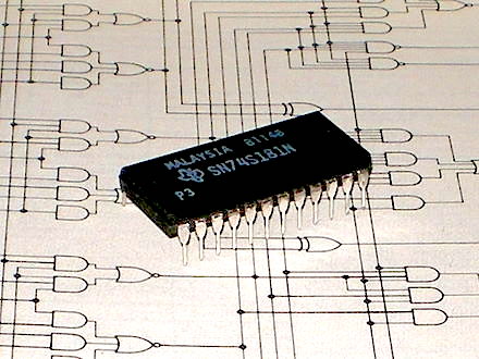
From its function table, I understood how the chip operates, including the variety of logic and arithmetic operations it supports.

However, after reading discussions about the 74181's internal design, I noticed a bit of division in the community. Some love it for its elegance; others think it's unnecessarily complex.
So, I decided to go with a more minimal and modular approach tailored to my own understanding. And instead of sticking with a 4-bit design like the original 74181, I upgraded to an 8-bit ALU. This gave me more headroom for meaningful operations while still keeping the design manageable.
OPCODE Mapping (8-bit ALU)
To control the operations, I created a simple 4-bit OPCODE system, allowing for 16 unique instructions:
| OPCODE | UNIT | OPERATION | DESCRIPTION |
|---|---|---|---|
0000 | AU | ADDC | Add with Carry |
0001 | AU | SUBC | Subtract with Carry |
0010 | AU | ADDO | Add with Overflow |
0011 | AU | SUBO | Subtract with Overflow |
1000 | LU | XOR | Bitwise XOR |
1001 | LU | NOT | Bitwise NOT |
1010 | LU | AND | Bitwise AND |
1011 | LU | OR | Bitwise OR |
1100 | LU | NAND | Bitwise NAND |
1101 | LU | NOP | No Operation |
1110 | LU | XNOR | Bitwise XNOR |
1111 | LU | NOR | Bitwise NOR |
Final Design Specs
FLAGS
| FLAG | Description |
|---|---|
OVERFLOW | Only for signed addition operations |
ZERO | Set if result is zero |
NEGATIVE | Only for subtraction operations |
CARRY | For additions exceeding 8-bit limits |
BUS Layout
| BUS | WIDTH |
|---|---|
INPUT_BUS | 8 |
OP_CODE | 4 |
OUTPUT_BUS | 8 |
STATUS_IN | 1 |
STATUS_OUT | 4 |
Workflow
My approach wasn't exactly linear — I leaned into an iterative workflow, learning from each version of the build. Each iteration gave me new insights and helped polish the final design step by step.
Design Implementation & Selection
I experimented with multiple logic gates and missed a few things here and there.
Here's my implementation for the AU, which is quite conventional.

Here, the AU performs the selection of operations:
| OP_CODE | OPERATION |
|---|---|
x00 | ADDC |
x01 | SUBC |
x10 | ADDO |
x11 | SUBO |

Similarly, the LU performs the Logical Operations:
| OP_CODE | OPERATION |
|---|---|
000 | XOR |
001 | NOT |
010 | AND |
011 | OR |
100 | NAND |
101 | NOP |
110 | XNOR |
111 | NOR |
Note: The lack of the last bit of the input OPCODE is because it will be used to choose between the AU and the LU.

Finally, this is the fundamental block for the operation of the ALU — the mighty 1-bit ALU.
Now that the hard part of designing the fundamentals is done, the more complex-looking block comes into play, where all of the smaller blocks are copied and pasted to get a final design like this:

This implementation of the 8-bit ALU is very basic and might contain unnecessary operations. Yet, I call it not unnecessary, as more or less all the required operations have to be implemented — and the added operations that are implemented within it are always dependent on the task to be accomplished.
Playing around with the final block, I implemented the input as 8-bit registers which can be manipulated by the user, and the output from the previous carry is fed back into the register as a part of operation in the ALU.

I personally didn't get into the HDL or VHDL implementation of these circuits, as they were quite irrelevant and out of my expertise at the time.